Power for Electronics
Power consumption
Positive power absorbs power, negative power produces power
For Single Phase Systems
Instantaneous Power
Instantaneous power is the rate of change of energy w.r.t time.
Average Power (Real/Active Power)
This is what does the work.
Formally
Where P(t) in the integral is instantaneous power (see above).
By using the definition of average power and RMS values above, and noting that the integral of a sinusoidal function over a period evaluates to 0, the following can be derived:
In a Resister this ends up being
In Inductors and Capacitors this = 0 since I will lead V by 90.
Reactive Power (Imaginary Power)
This exists because of inductors and capacitors
In the leading case, theta_v - theta_i is negative, so the angle of which we take the sin is ”-“
This is the opposite, in resistors this is 0 (in phase)
In Capacitors and Inductors this is
Complex Power (S) We will use this :)
You can also have complex power which is
Where P is the real part of S and Q is the imaginary part of S
In its full form…
If theta_v leads theta_i, the load is known as an inductive load.
If theta_v lags theta_i, the load is known as a capacitive load.
In both these cases, there is a real and imaginary component to the impedance.
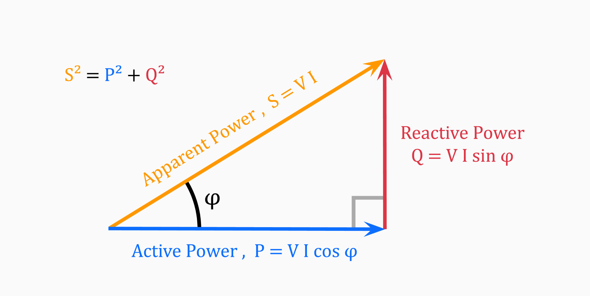
Apparent Power
This is the magnitude of complex power.
Power Factor
PF is Real power / Apparent Power
PF = 1 when theta_v-theta_i=0 and S=P, (this is the most desirable PF because you are the most power efficient)
Lagging and Leading
If I lags V we have an inductive load (lagging PF, PF < 1) If I leads V we have a capacitive load (leading PF, PF > 1) If I is in phase with V we have a resistive load (unity, PF = 1)
Power Triangle

Power Factor Correction
Loads are usually inductive (lagging PF).
means power is absorbed by the load (Inductive load).
Q < 0 means Q is delivered by the load (Capacitive load).
Idea
So basically the idea here, is since most loads are inductive, we want to put a capacitor in parallel with an impedance Z such that we move |S| as close as possible onto the Re axis (making PF = 1).
Finding a capacitance needed for correction can be done by finding Q_old using the reactive power equation and then using
with and rearranging to solve for C.
Three Phase Y-Connected Power
where
This yields the phase angle between voltage and current which is the same as our previous definition.
Line Impedances
Line impedances cause a voltage drop across a line and influences the electric properties of a source.
Using Line Impedances
When solving 3-phase systems (line current, power, power factors), line impedances should be added to the given Y-connected load.
Remember
Line impedances will affect the power factor of the source! The load power factor is independent of the system and only depends on the load.
Hysteresis
Where the energy lost is the area under a hysteresis loop
Where:
- K = const
- V = volume
- n = an empirical number
- f = line frequency
There is a second element of core loss which is the eddy current loss. Therefore, the total power core loss is:
Power For Deformable Solids
Power . s torque times speed
A convenient conversion with speed in rpm
Where:
- H: Power
- n: Angular velocity (rpm)
Using US customary units
where: