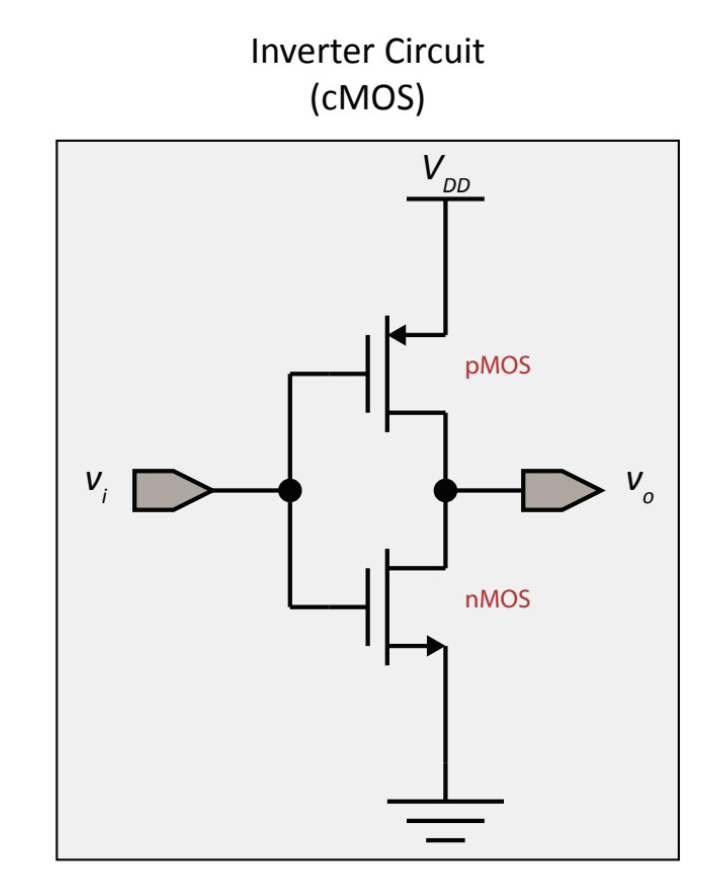
Basically functions as a digital switch.
Notation
Hierachy (from top to bottom) Active: Transistor Driven Passive: Resistor Driven Floating: Hi-Z
You shouldn’t have two active or two passive etc because this causes uncertainty and also damage to your system
Inverter Networks
PMOS’s are connected between the source and the output (active source)
NMOS’s are connected between ground and the output (passive source)
You can use both transistors and no resistors to create a push-pull network which are both active

We tie the behaviours together here to primarily make sure we don’t get conflicts.
Since its so easy to build an inverter (using these transistors builds an inverter by default), we can add another lead inverter so that our outputs are not flipped
Avoiding Large Current Flow Conflicts
Permanently:
- Use a passive pull up resistor or a passive pull down resistor to limit current flow (1 active and 1 passive so its good) Temporarily:
- Disable a device by turning off all its transistor controlled connections to the power supply and ground
Now that we have that down, see Drivers.
Review
I’m a little weak on this topic and Drivers in particular because of the electronics so I’ll need a review