A microprocessor consists of only a processor.
Usually refers to a CPU.
A microcontroller is a complete computer with a processor, memory, and I/O for peripherals.
Elevating this concept, a system-on-a-chip (SoC) is a fully functional system on a single chip.
Elevating this concept further, a system-on-a-programmable-chip (SoPC) is a reconfigurable programmable logic device.
CPU
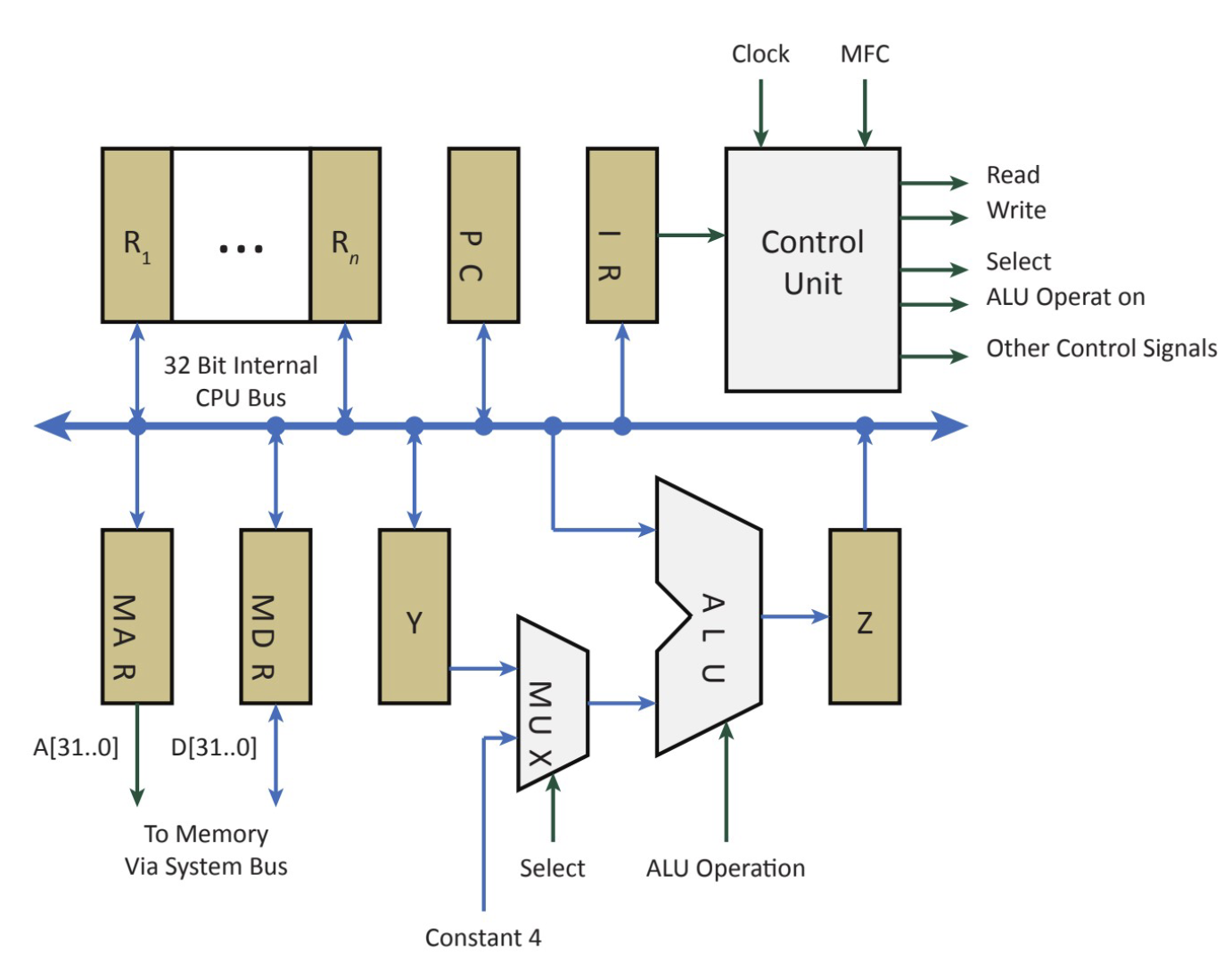
In a simple microcontroller, an MUX chooses between passing data, or a constant 4.
4 is an option since memory is byte addressable, you need to add 4 bytes to get to the next address and that happens often, so its useful to have 4 bytes handy through an MUX.

Parts of the CPU
Memory Data and Address Registers
The internal bus, and interacting with everything else in the system passes through these two registers. Not directly accessible to the programmer.
Copied from my notes lol oops
MAR (Read/Write)
Unidirectional and can be written to by the internal CPU bus and read by the external system bus.
This holds the address of the current instruction that is fetched from memory
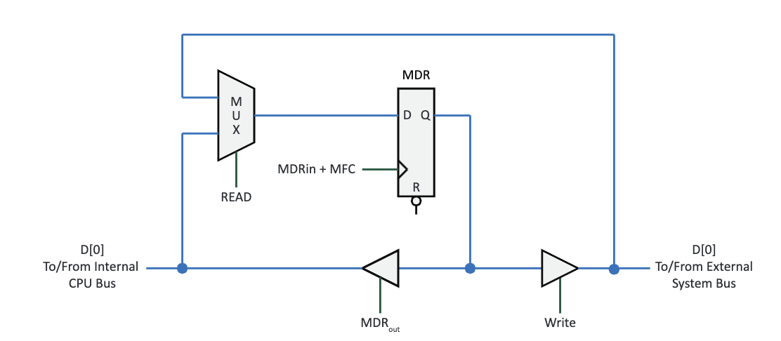
Has a D register:
- Data (D from the CPU bus)
- A Clock (MAR_in driven by the CPU)
- Output (Q, some address in the system bus) How it works:
- The CPU places the address of the next instruction in the MAR
- the address is sent from the MAR to a memory unit
- The instruction from that address is placed in the MDR
MDR (Read/Write)
Holds the data found at the MAR address that needs to be transferred The MDR must allow allow both the internal and external CPU and system busses to read and write to it without conflicts (sync).

For writing:
- READ needs to be 0 (this is the synchronizer) to make information from the internal CPU bus available at D
- On a rising edge of MDR_in, the data is loaded into the MDR
- When the system bus is ready to complete the write, the write signal (tristate) will be enabled (set to 1) making the data available to the external system bus For reading:
- This means information needs to pass the opposite way
- Information goes from the external system bus to the internal CPU bus
- We set READ to 1 to make data from the external system bus available at D and then the MFC signal will clock in the data to the MDR
- When the CPU is ready for data, it sets MDR_out (tristate) to 1 making the data available to the CPU bus
Memory Function Complete (MFC)
A sign that tells the CPU that the current activity using memory is finished (data is ready to read, or data is finished being written. This is the only signal driven by memory.
Memory Timing
The CPU asserts the address value causing the memory to EVENTUALLY respond with a corresponding data value. There is some delay between a request from an address and getting the data back.
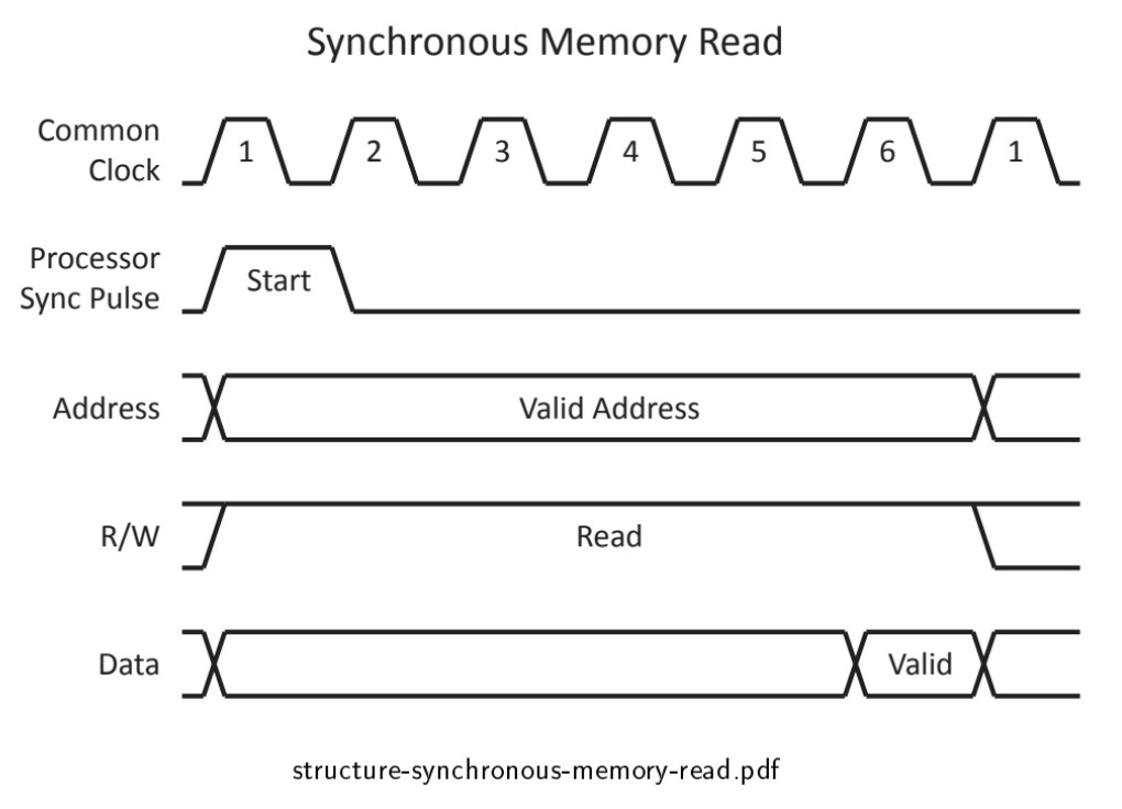
The Synchronous Option
The CPU would assume that data is valid only after n clock period where n is the number of clock periods needed to respond to a CPU request for data.
Memory must provide data before the end of the nth clock period
Fixed predictable amount of time

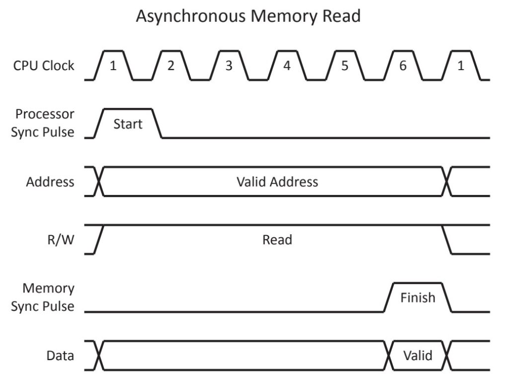
Asynchronous Option
The CPU and memory exchange time synchronization signals (basically processor sync pulse is sent when a new memory operation starts and a memory sync pulse or a flag is sent when data is valid)
The memory pulse and data are memory driven
Faster because you get a signal from the peripheral to take action

Sharing a Bus Line
What if the outputs of two AND gates are directly connected to the same line of a third AND gate? Then the value of one of the gates would be lost if they have conflicting outputs.
Sharing a bus line
We need a mechanism to uniquely select at most one output driver at a time, or you need to connect the output drivers such that conflicts do not result in large current flows.
Sourcing and Sinking Current
- When sourcing current, the output driver connects a voltage source
- When sinking current, the output drivers connects to a voltage sink
- When in high impedance, no connection exists
The thing producing the signal is the output driver and the input driver is the pin on the microcontroller.
Sourcing and sinking currents is viewed from the output drivers perspective.