A note on notations
For this section, we use to mean “moment” to be consistent with Shigley’s texbook.
A note on weight
In MTE 321, we neglect the contribution of weight forces in our dynamic force analysis since its usually negligible compared to kinematic acceleration. If this isn’t true for a mechanism, you may need to rethink this assumption.
Fundamentals
Mass Moment of Inertia
Defined as and depends on the axis that a body is rotating. For planar kinetics this is perpendicular to the plane of motion (rotation about the z-axis)
Radius of Gyration and Composite Bodies
The Radius of Gyration is a measure of the distribution of the body’s mass about the axis of which the moment of inertia is defined
Composite bodies are created from adding together the moments of inertia that make up a shape
Important shapes
Cylinder
Sphere
Plate
Parallel Axis Theorem
Used when rotation is NOT happening at the COM
Parallel Axis Theorem
- Basically here, break down a body into simple shapes, find their COM’s and add them
- Then calculate the MMI of the simple shapes
- Then use this equation to find their corrected MMI where d is the distance between the COM of the shape and the global COM found in step 1
- Then add up the MMI of the shapes, now you have !
- You can find the radius of gyration now using
Analysis
Also known as “Inverse Dynamics”
Single Linkage
For any rigid body with general plane motion, we have 3 equations of motion
Assume a rigid body with mass of m, on the x-y plane with a moment acting in the z-direction.
What is important here
- Need the centre of mass
- Need mass of link
- Need link length (to make position vectors which are our lever arms for torques and for the )
- Need (mass moment of inertia about the centre of mass)
The unknowns here are the x and y pin forces and their moment (driving torque)
In scalar form:
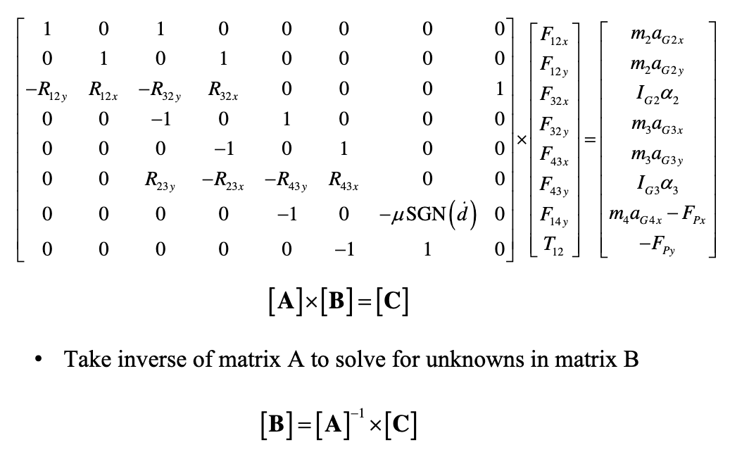
You can put this in matrix form to solve as a set of linear simultaneous equations and then take the inverse of matrix A to solve for the unknowns in matrix B which are our x and y forces, as well as our moment.
You will have 9 unknowns in total to solve for in a planar 4-bar mechanism For a single link, you have 3 unknown forces and moments. We can use Matlab or a matrix solver to do this for us.
Solving
Note that in an exam we would only have to set these up
Four Bar Linkage
Just an extension of the single bar linkage problem
- Kinematic analysis should be done to solve for linear and angular accelerations first
- Get link lengths, positions and the position of the centre of mass
- Get mass of each link
- Get of each link
We solve each linkage using the single link equations above which yield a 9x9 matrix with 9 unknowns and the process is the exact same.
Making the matrix
Your B vector is a vector of all your forces, your resultant vector is the right side of the newtons 2nd law equation or , sometimes the position and force vector of your POI will be in this vector. Forming the matrix involved putting 0s and 1s in the right places to form your equations and placing position vectors R where they need to be to create the moments that exist.
Notes from solving
- Find coupler dimensions (the piece that moves the mechanism from an external force)
- Identify the given angles and derivatives
- Do kinematic analysis to get and
- Calculate the distance from links to their centre of gravity
- Find m and I for every moving link using their density ( btw) and for a rectangle about the z-axis (mass moment of inertia)
- Set up the local non-rotating coordinate system and label position vectors
- For this, notate on the mechanism the forces (forces are at each joint), accelerations (accelerations are at the COM), and position vectors (these go from the COM of a link to the joint of the next link, so most links will have 2 position vectors in opposite ways)
- When you write the equation of these position vectors, the formula goes where the 180° may or may not be there depending on the orientation of the vector
- Find the X and Y components of all 4 accelerations using the linear equation from Acceleration Analysis
- If you are a link that is not grounded, your acceleration is a coupled acceleration dependant on the acceleration of the entire link you are grounded from and the acceleration of your COM to that link ex. where a is a linkage connected to link 3
- Find the X and Y components of the external force
- Assemble the solving matrix (furthest we will have to go)
