We use Tri-states to separate out different address lines so that we only get the line that we want to go through when the right tristate has its enable bit on.
Clock Signals
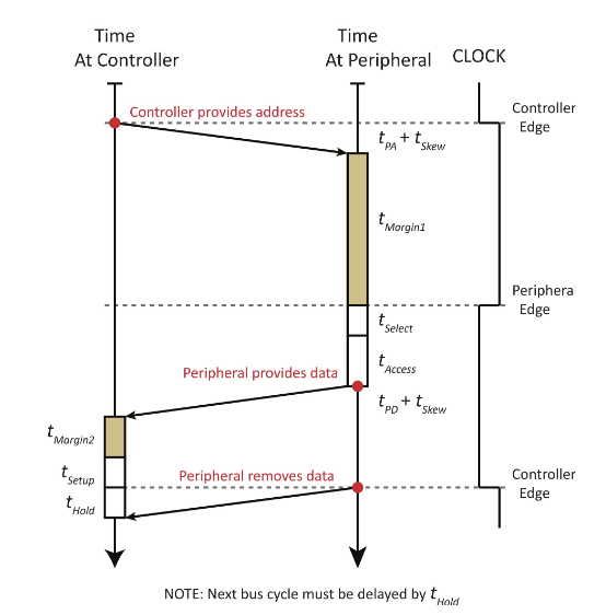
- The rising edge says “this is the start of a transaction”
- The falling edge says “this data is now valid and can be read”
Flow
- The controller starts a transaction and specifies a read
- We wait for controller propagation and skew time (specifying a read has propagation but no skew time)
- We then wait for margin time which is just safety factor time which ends on the falling edge of the clock
- Then we wait for the select time which is the time it takes for the peripheral to realize that its being selected
- Then we wait for access time which is the time it takes the device to access the requested information
- Then the peripheral provides data to the controller
- Then we wait for margin time, setup time which is the minimum time that a signal has to be available before an active clock edge, then the hold time which is the minimum time the data can be held stable during a read and occurs on the next rising clock edge
- After hold time, the peripheral removes data from the controller so another transaction can happen

Sequential Read and Writes
Normally if a write followed a read we would have to skip a cycle but for this course, we will assume that t_hold is = 0
Exam Problem
Timing Diagrams are common on exams (probably synchronous bus read and write)
Duty Cycles
Note that when graphing this, if there is a duty cycle, that would just be the clock high time instead of arbitrarily choosing an optimal duty cycle that sets a falling edge right after t_pa :)