Transformers
Robots in disguise
Stationary electrical energy transfer devices.
Transformers are machines but instead of changing the type of energy provided, they change the levels of voltage and current and provide isolation.
Transformers are very high efficiency 92-99% usually.
Single Phase
Stepping Up or Down Voltage
Done using a turns ratio
Voltage and Current Measurement
Isolation
Impedance Matching
Max power transfer occurs when
Transformer Structure
Types of transformers
Core Type Transformers You have two segments (U and I) which form a square, where U and I are stacked in alternating fashions.
The windings go on the left and right legs but experience high flux leakage.
Voltage drops under load.
Bad voltage regulation in the core.
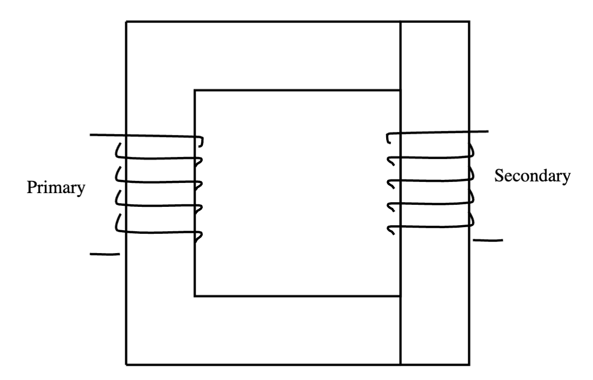
Shell Type Transformers
You have two segments (E and I) laminations where they are stacked in alternating manners.
The windings go on the same a leg and:
- reduces flux leakage
- Theres less voltage drop under load
- There is better voltage regulation
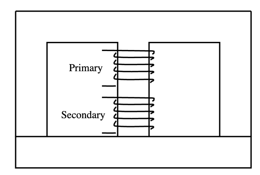
Equality of MMFS
When theres no voltage drop because reluctance in a circuit is 0 in an ideal transformer…
The power transfer from one side to the other is also lossless.
Making noise
In response to the magnetic flux in a transformer core, the core expands and contracts which causes noise (magnetostriction)
Internal Forces are exerted on laminations due to eddy currents and a magnetic field according to
Therefore, the frequency of force = 2x the frequency of excitation
Types of Cooling for Transformers
- Air cooling
- Oil cooling
Dot Convention
Denotes on which side the positive terminal is for a transformer
Principle of Operation
In an ideal transformer
Also note that
If…
- a > 1 ⇒ E_s < E_p ⇒ Step down
- a < 1 ⇒ E_s > E_p ⇒ Step up
- a = 1 → E_s = E_p ⇒ Isolation
but more importantly in practice:
For impedances
The Short Circuit Test
The short circuit test is performed to find the internal (thevenin) properties of a transformer
Impedances
The power dissipated during a short circuit test is due to the resistive component of impedance
The equivalent impedance (thevenin impedance can be calculated using the short circuit voltage and current)
Using the two found impedances, you can find the inductive component of impedance :)
MEMORIZE THIS EQUIVALENT CIRCUIT
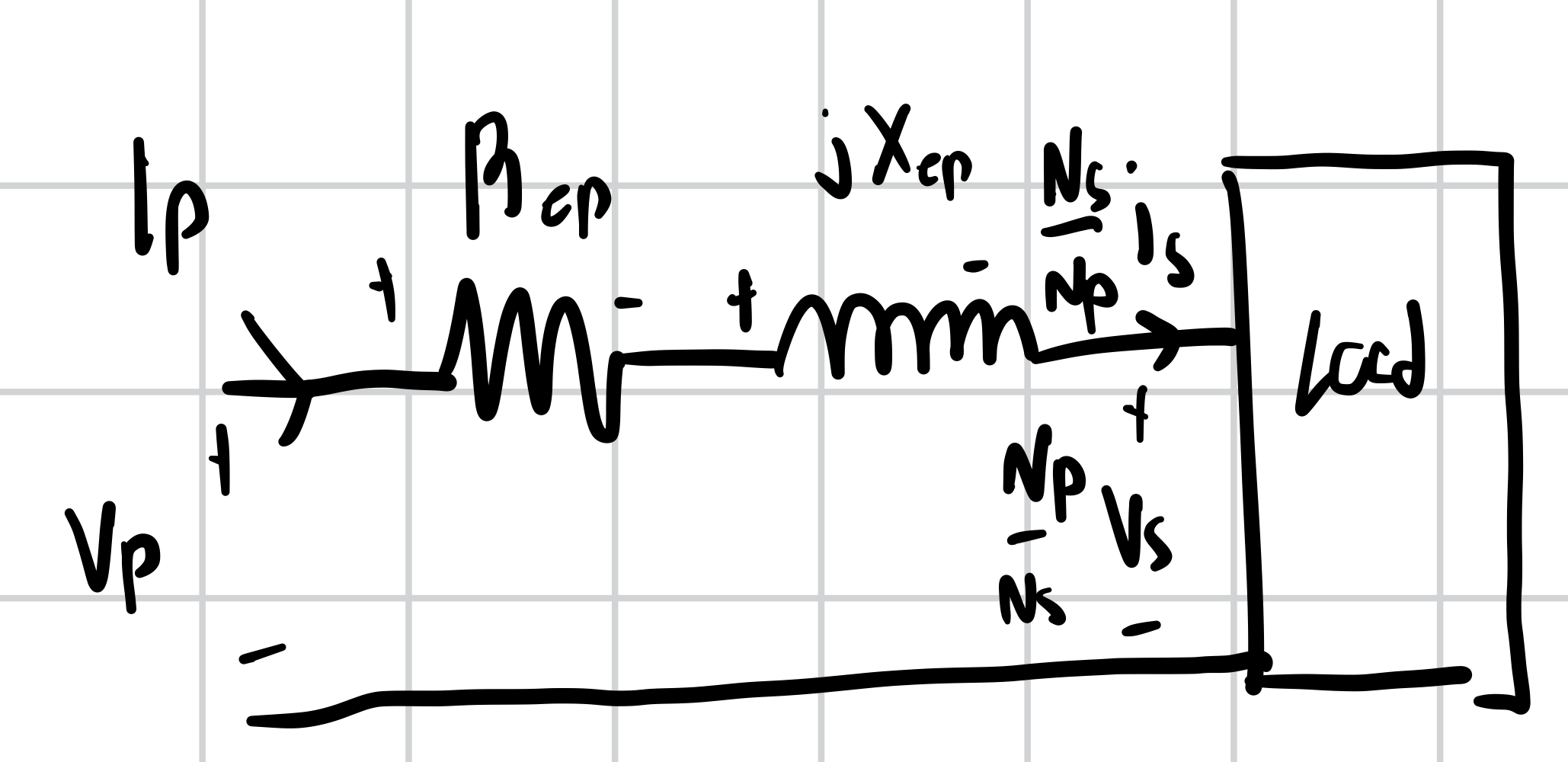
By finding R, and X, you can use the given information and this model to find whatever you need in an ideal transformer (using KVL)
When to use different types of power:
- Use |S| when analyzing the overall transformer
- Use P when calculating efficiency and output power (caused by R)
- Use Q in the same situation as P but for impedances
- Use P_sc determining equivalent RESistance of a transformer (real)
Ignoring Winding Resistances and Inductances
In this case you don’t need to draw the model, you can just use the relationships outlined before this and solve for things…
Not that when using a power factor with power on the loading side to find current…
We divide apparent power by the power factor
In the real ideal case where we consider winding resistances and inductances, we use power factor to find the phasor angle of current
Ideal Transformers and Non Ideal Transformers
Ideal Transformers
- No impedances
- No copper loss
- No core loss
- No eddy loss
- No reluctance which yields infinite permeability
Midterm Cutoff
The Midterm content stops here!!!
Non-ideal Transformers
- Non-zero reluctances and lengths
- Non-zero core loss and leakage flux Drawing non-ideal equivalent circuits
- Both the primary and secondary sides have
- An equivalent resistor
- A reactance inductor
- An e_p across the transformer terminal
- There is technically a branch from the top to the bottom that include a R_c and X_m resistor and reactance which induce core-loss, where we say that R_c and X_m are very large which prevents current from flowing down the branch so this isn’t considered in circuit analysis but is considered when calculating power
No Load on non-ideal transformers
When there no load, I_s = 0 but I_p and I_o are not 0
- Core loss is calculated with
- Non ideal voltages can be calculated using
- I_p = I_o since there is little current running through the transformer with no load
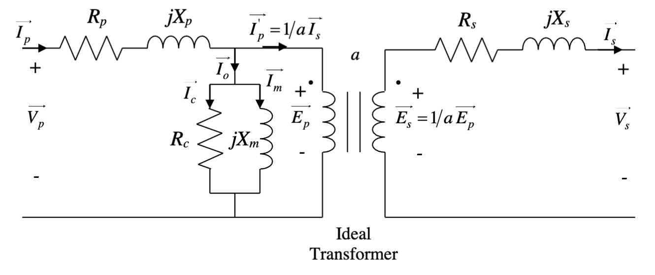
Under load
When load increases:
- I_s increases
- Flux decreases
- E_p decreases
- I_p increases
At steady-state
This means the transformer reacts to changes in load by making changes to the primary current
Simplifying the Equivalent Circuit
You can connect the two sides of the transformer equivalent circuit by:
- drawing one equivalent circuit where the two sides separated previously by the transformers are connected except the secondary side is modified by the turns ratio
- These are the reflected currents, impedance, and reactances from the primary winding side to the secondary side and can be derived using the principle of operation of an ideal transformer for current, voltage, and impedance
This helps in circuit analysis since we can refer to everything in terms of the primary or secondary side and combine our separated circuit into one equivalent circuit
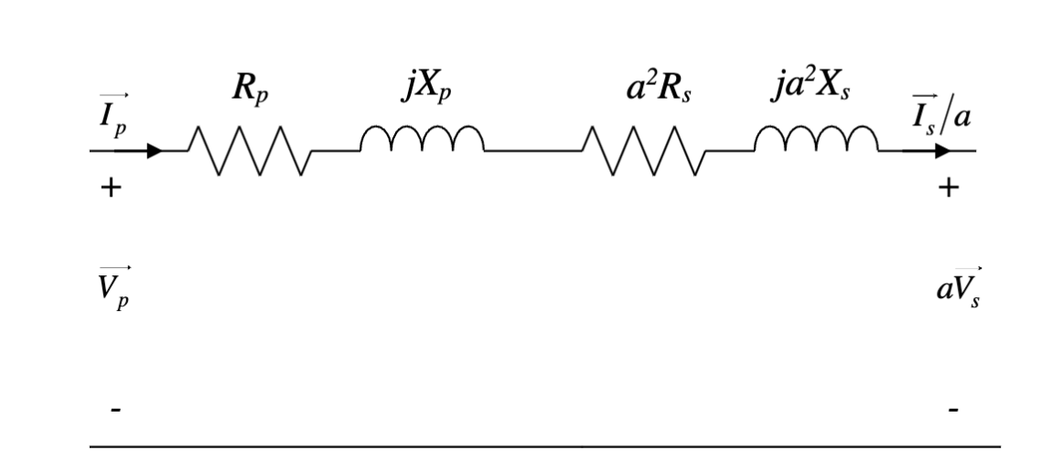
Transformer Tests
Determine transformer equivalent circuit parameters.
Open Circuit Test
- Open circuit terminals of high-voltage side of the transformer
- Apply rated voltage to low-voltage side
- Measure power, voltage, current on the low-voltage side
- The power measured by the wattmeter is equal to the core loss
- Using measured power and open circuit current (current through the shunt branch) you can find R and Z which you can use to find X
Short Circuit Test - Short circuit terminals of the low-voltage side of the transformer
- Apply a reduced voltage to the high-voltage side so that the short circuit current read by the ammeter is at most equal to the rated current on the high voltage side
- Measure power, voltage, current on the high-voltage side
- Power measured by the wattmeter in a short-circuit test is equal to the copper loss of the transformer which is the I^2R loss in the resistances of both sides
Voltage Regulation - Don’t need to consider the shunt branch here
At the primary side:
At the secondary side:
Or in both cases: Where NL and FL refer to no and full loads respectively
Efficiency
Where the power losses come from copper and core losses.
Expanding on this formula…
When P_load increases, efficiency increases.
Note that when decreasing the load,
All-Day Efficiency
Transformers have different efficiencies at different times based on the loading level
Transformers have different efficiencies at different times based on the loading level. Utilities use an all-day energy efficiency
Auto Transformer
The primary and secondary circuits and electrically connected.
These types of transformers are common for circuit tests.
Note that we should not connect the full voltage to the circuit since unpredictable accidents can happen.
Instrument Transformers
Special designs of transformers are used to measure high voltage and current.
Potential Transformer
A potential transformer used to measure a high AC voltage.
We primarily use this to reduce the line voltage to a level that is acceptable for measurement which is done with a turns ratio.
When a live transformer is connected to a live system on the primary side, the secondary behaves as a voltage source so DO NOT SHORT THE SECONDARY TERMINALS.
Current Transformer
Similar to a potential transformer, a current transformer is used to reduce the line current to an acceptable level to measure.
Also similar to a potential transformer, when a current transformer is connected to a live system on the primary side, the secondary side behaves as a current source so DO NOT OPEN THE SECONDARY TERMINALS otherwise high currents can damage the transformer.
Impedance Matching
To maximize power delivered, load resistance must equal source resistance.
Since we theoretically cannot control the load resistance R_l, we can place a device as seen from the source side such that the load resistance becomes equal to the source resistance.
To do so, a turns ratio of
should be chosen.
For complex impedance matching
should be the complex conjugate of
Practical Transformers Tips
- An equivalent circuit of a practical transformer is a joined equivalent circuit of the primary and secondary sides where things are usually referred to the primary side with the shunt branch connecting the positive rail to the negative rail
- Here, you just solve from one side to the requested side
- To solve for voltage, current etc on the opposing side given the primary or load voltages, we need to translate to a linking voltage / current (usually current) and then use simple KCL and KVL to find the voltage / current that we are looking for remembering to consider the shunt branch in our circuit analysis, a useful equation is which can be used to find primary voltage, also remember that
- To find transformer efficiency, we need to find the real power output which is the output current multiplied by the output voltage (load rated voltage) and then the power losses (copper and core losses) which are the losses from the primary and secondary impedances and the losses from the core
- If we’re finding voltage at the load, we need to put our load impedance in terms of the primary side by multiplying by , find the impedance seen by the primary side considering the shunt branch and then use voltage divider to find the voltage at the load using the primary side impedances as well
Three Phase Transformers
The primary and secondary sides can be connected in the ways described in Three Phase Circuits.
Similarly, three phase transformers can be treated as three single-phase transformers where most delta connections are converted to a Y connection before analysis which can be solved where succeeding voltages and currents and phased-shifted from the previous voltages and currents.