See MTE 321 Lecture 2.
Sign Conventions
+ Shear Force causes CW rotation of a beam (left part goes up, right part goes down)
+ Bending Moments cause compression at the top of a segment
Internal Shear and Bending Moments
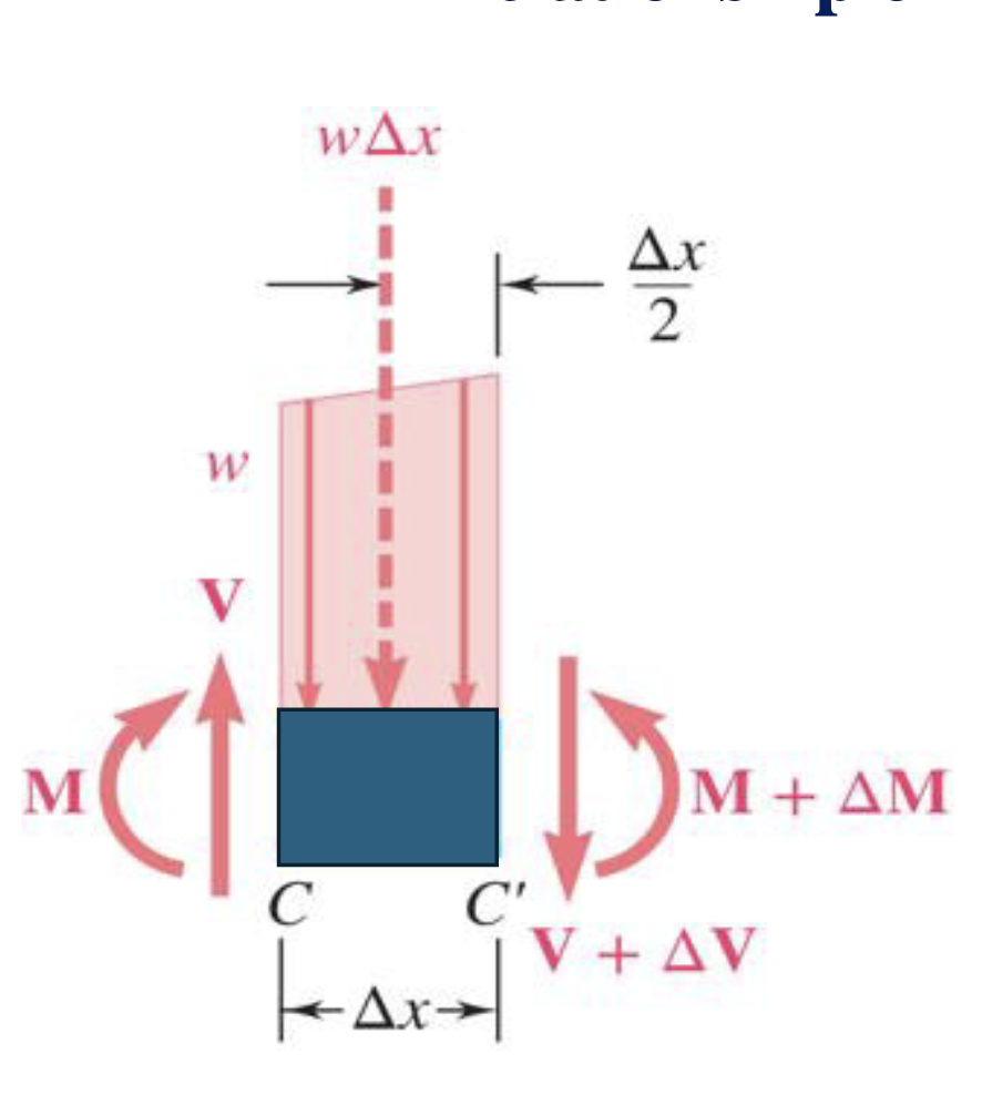
When you split a distributed load you get two components with a shear force, and bending moment that make each member bend inwards.
*Downwards shear and CCW bending moments are +!
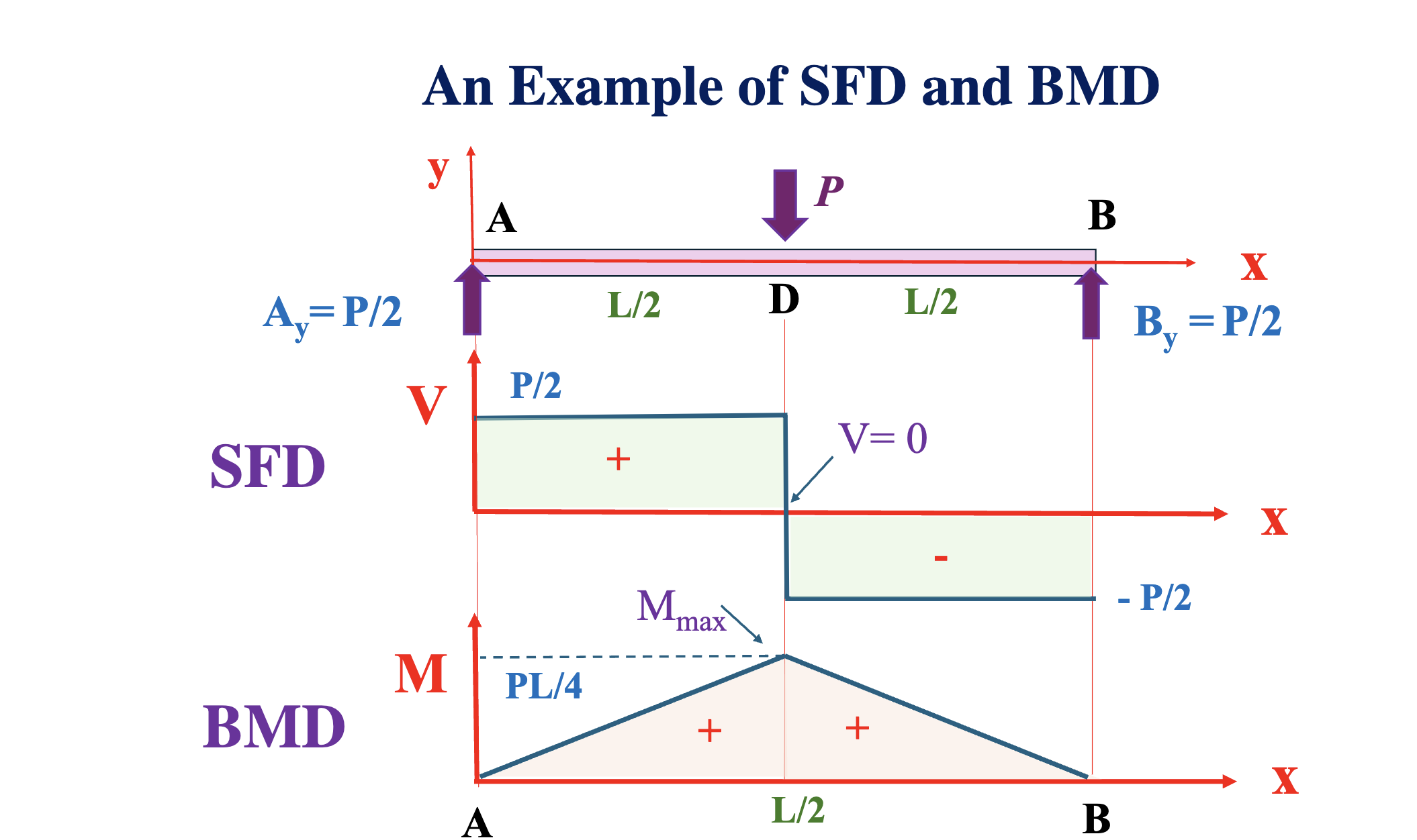
Example SFD and BMD

Tips for SFD and BMD
- Make your internal cut to minimize the amount of unknowns on a section
- For the beam shown above, you need to make 2 cuts for enough equations to solve for V and M due to the presence of P
- Brute Force: basically, you need a section for each “segment” capped by a transverse load, that way you can solve for V and M and use that solved value for V and M to carry over to the next segment
- When V is 0, M is at at a critical point
- Diagrams should start and end at 0
- Graph the results by connecting the dots
- This way is tedious and disconcerting but provides built in error checking
- We want a better way to do this to save time…
Better way via relationships
- Start at whatever your left-most reaction force is, and then the SFD reacts to transverse loads as you go along the beam (pushes your diagram up, or pulls it down).
- Use the AREA under the SFD to find the maximum value of M at the next point of interest (next transverse load)
- When V is + M slopes up, when V is - M slopes down. M is also one degree higher than that of V.
- Connect the dots
Load and Shear (Shortcuts)
The relationship between load, shear and bending is as follows and yields a nice way to model shear and bending forces

This ultimately yields:
and
Diagram Considerations
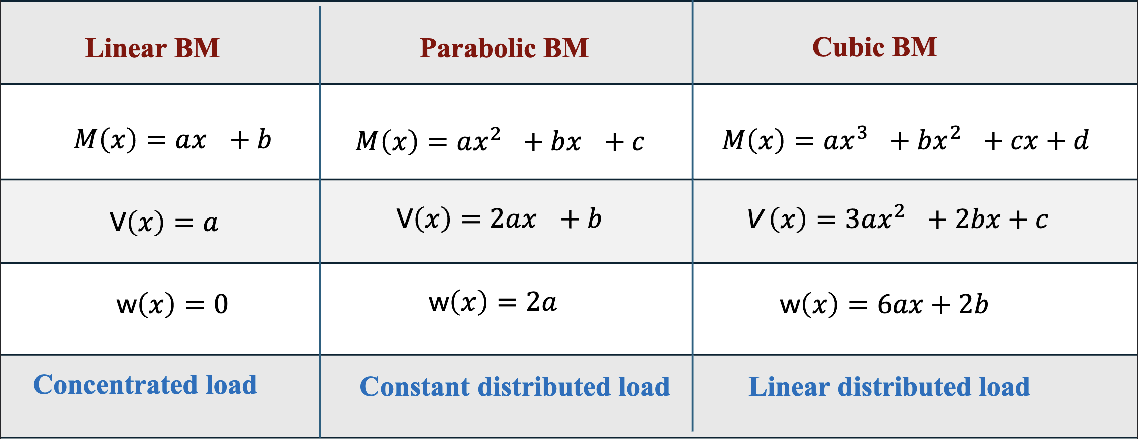
- Between concentration load application points, shear variation is constant
- Between concentrated load application points, the bending moment is linear

Uses in Beams and Loading:
- Determining shear forces and bending moments produced by applied loads
- Selecting cross-sections best suited to resist shear and bending forces