Mohr's Circle
Preventing failure, a design needs to account for maximum stress resulting from normal and shear stresses
The Mohr’s Circle:
- Studies the combined state of all stresses
- Helps identify max stresses
- Is a visual representation
Using the equation of a circle:
where :
:
:
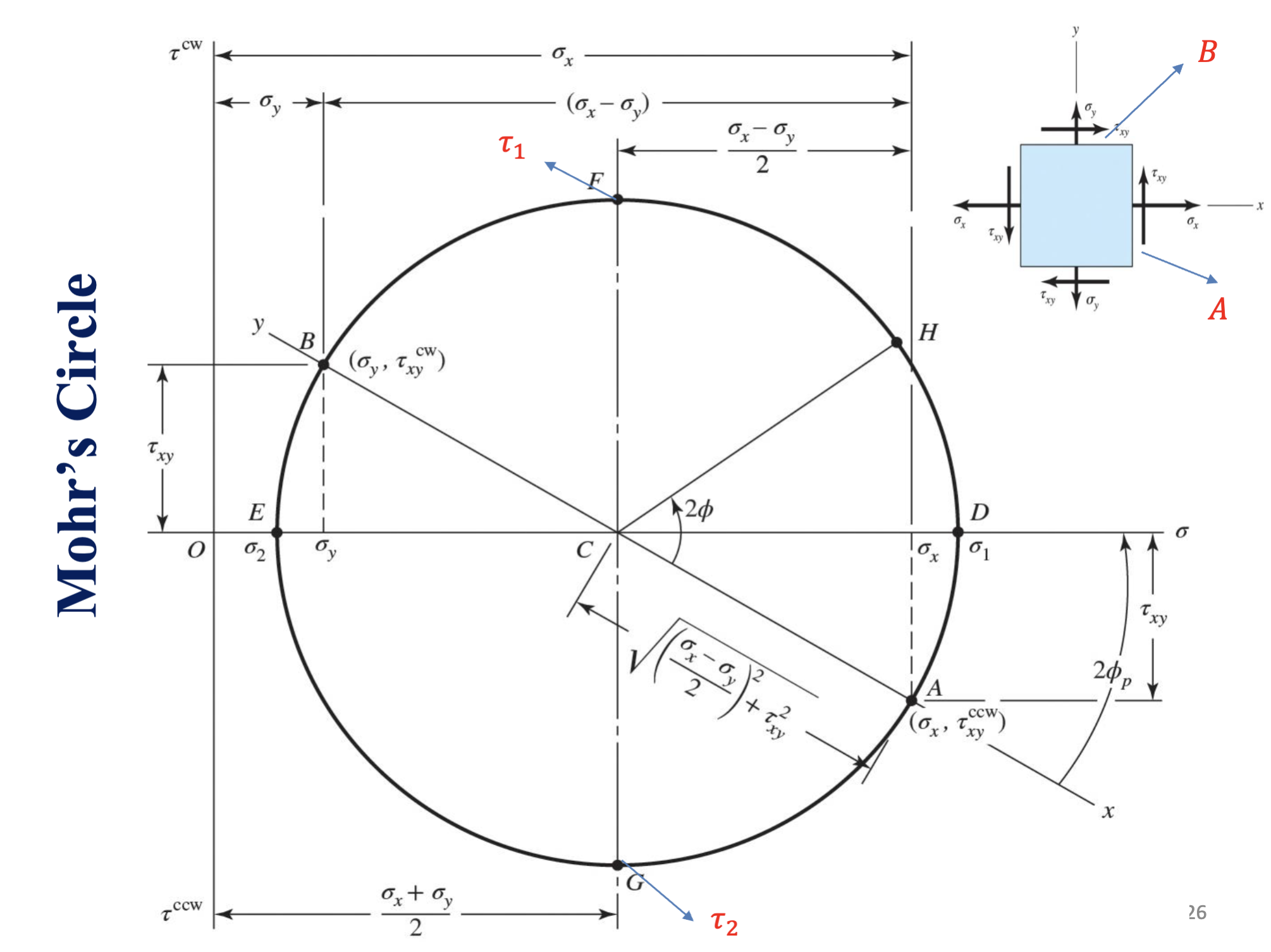
Diagram

Where E in minimum stress, and D is maximum stress.
The top face of a Stress and Stress Transformation diagram is point B, and the right-most face is point A.
Conventionally:
- Shear stresses that rotate an element clockwise are above the sigma axis
- Shear stresses that rotate an element counter-clockwise are below the sigma axis
Drawing a Mohr’s Circle
- Locate the center C =
- Find CD
- Locate the face of A
- Locate the face of B
- Connect A B and C and draw a circle
- Use geometry to compute the rest (principle stresses, max shear stress = R, principle angles, etc)
Mohrs Circle Angles
Angles in a Mohr’s circle are doubled (the angle between C, A, and the sigma axis):
Orientation
Max shear and average normal stress are always 45 degrees rotated CCW from max normal stress ()
More on orientation
The sign of is determined by the sign of tau_xy (+ = cw)
If one is cw the other is ccw!
When determining angle we are either subtracing 45 degrees from , or form 45 degrees. If > 45 degrees:
otherwise:
In 3D
Now there are three principle directions and stresses

There are also 3 principle shears now
