DC Machines (Generators)
Note that l is usually collinear with v x B such that the expression is simplified to…
Also note that if v x B is perpendicular then…
which is the largest emf that can be induced in a generator.
Where if its not given and
Most DC machines are designed geometrically to observe these optimizations.
Generator or Motor?
If then we have a generator. Otherwise, the machine operates as a motor. You can also tell depending on the sign of the armature current, + = generator, - means motor.
Note that for a standard diagram of a DC generator…
The voltage for a conductor loop (summing the emf in all segments) is:
Where the voltage is reversed when the terminals are reversed, meaning the induced voltage between terminals A and B is:
or or
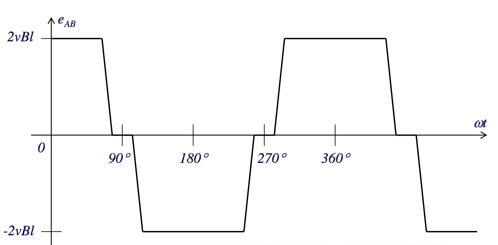
This creates a staggered sinusoidal waveform that looks like this:
Generation by Commutation
Normally, the induced emf is alternating, in this method, there are commuter segments which are half semicircular conductive loops that rub against stationary carbon brushes which are the terminals of the generators.
Irrespective of the position of the loop, the polarity of the output remains the same so the output voltage is the rectified version of called .
This shifts the figure above up, such that the lowest amplitude sits at 0V.
Breaking this down
- As the armature spins in the machine, it moves through a magnetic field which creates an emf in the armature windings
- There are commuter segments that are connected to the ends of the coils which get touched by brushes as the armature rotates
- As the armature rotates, the brushes touch different commuter parts which reversed the direction of current in the armature windings which reversed the voltage direction keeping it all in the same direction
Improving the Waveform
Right now, there are large ripples in the waveform and the voltage is low, this can be improved by increasing the number of coils of wire on the rotor.
By how much, is specific to a case.
Electrical and Mechanical Angles
In a 2-pole machine:
Where 1 revolution of the rotor corresponds to 1 cycle of the generated voltage.
For an N pole machine:
Some Intermittent Definitions
Armature: the windings on the rotor where the emf is induced
Field: Where the excitation is placed in the statorArmatures can be classified in the following:
- Lap winding has P parallel paths in the windings which are used for high current devices
- Wave winding has 2 parallel paths used for high voltage applications
Induced EMF General Formula
Where…
- Z = number of series conductors calculated using
- a = Number of parallel paths
Building on this….
and where where P is the number of poles.
Thus….
Where , there is also a frequency representation of in the course notes but you can just convert frequency or rpm to and use this representation.
Generation of Torque
Since F is…
and Torque is produced by
Two forces from two conductors that have the same magnitude and direction yield:
In the arbitrary case we have for Z conductors.
Also note that B here is flux density
For Speed Control
Where is the frictional torque.
To increase we want
Otherwise, to decrease speed, we want
Counter Torques
In the presence of a magnetic field, a force and torque will be develope din the conductors which will oppose the original torque. The torque applied by the prime mover is called the counter torque and is:
Where
The Armature Reaction Problem
Armature Reaction
Caused by the interaction of magnetic fields of the stator and the rotor.
No armature current magnetic flux pattern is normal.
When the rotor rotates 90° such that the linear speed is parallel with the magnetic field the induced voltage will be 0. This is the exact moment commutation takes place, where the brushes short the commutator segments. Here, no sparks are produced.
Due to armature current, a magnetic field is set up that weakens the current magnetic field of the stator in some areas and strengthens the current field in other areas. This shifts the magnetic neutral axis. When the neutral axis is shifted (which corresponds to the position of the brushes), the switch between commutator segments takes place when the induced voltages are not 0 causing sparking which increases with armature current.
Sparking accelerates wear in the brushes and commutator segments due to local heating.
Solutions
Solutions to this problem involved moving the position of the brushes to the new neutral axis but this is not known before-hand. A dynamic solution is to use dynamic windings (compensating windings) which carry armature current in such a way that the produced magnetic field opposes the rotors magnetic field at the pole tips.
Equivalent DC Machine Circuits
Series DC Motor
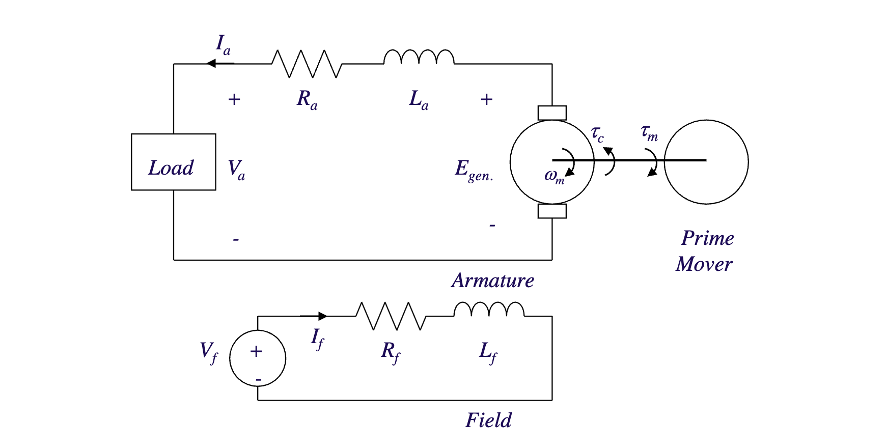
At Steady State
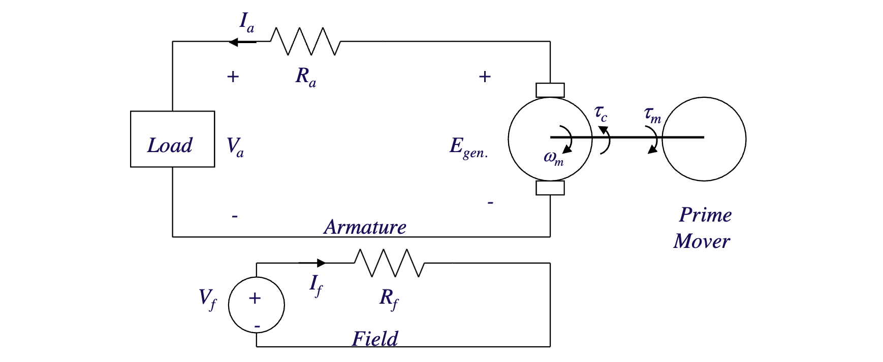
And the steady state equations consist of:
Other main relationships here consist of:
From KCL
Series Stuff
In theory… the no load speed () is infinite and the starting current causes the starting torque to be very large
Note that and is basically just a frequency conversion?
Note that when is 0, is not zero due to a residual flux.
Notes on Series Motors
The starting speed of a DC motor is very load dependant so we should never start a motor with no load. We usually use tis motor where a high starting torque is required.
Separately-Excited DC Motor
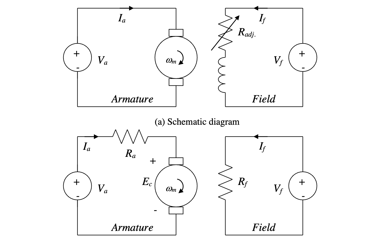
Main Relationships
Shunt DC Motor
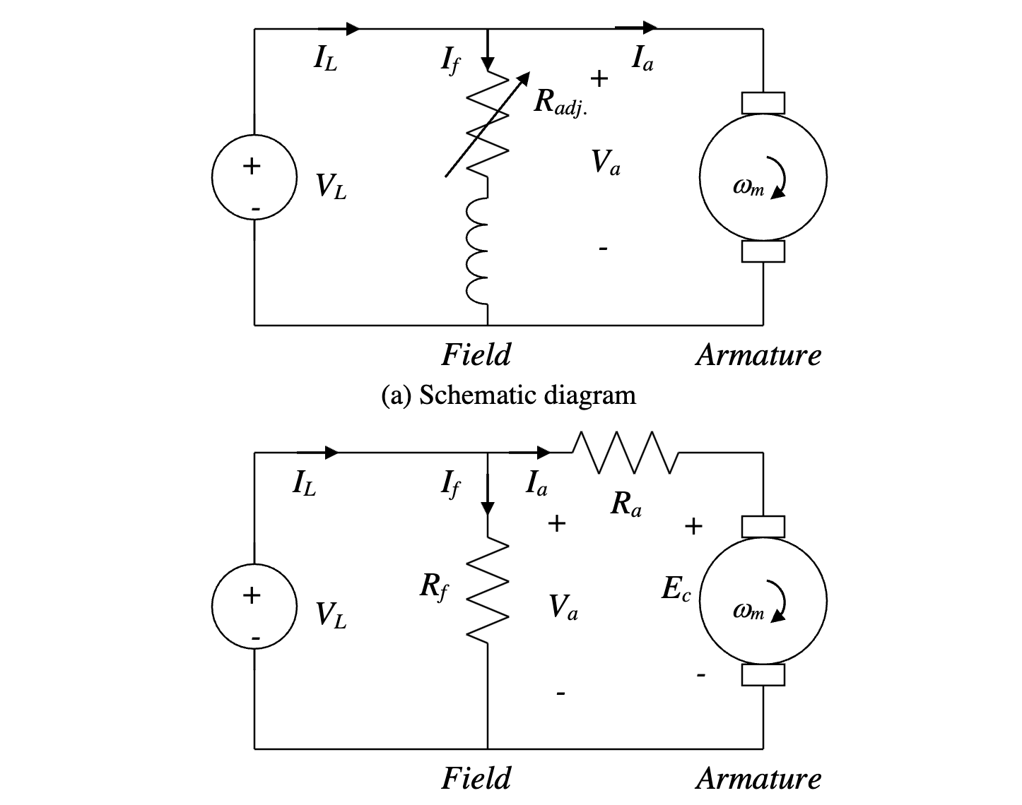
Main Relationships:
When V is constant, this is the same as a PMDC, but when it gets smaller both and get smaller as well
Starting
We can’t start a shunt DC motor from standstill since it creates a very large . We need to limit the starting armature current using a starting system
Manual Starter
This essentially uses a manual variable resistor placed in series with the armature of the DC motor. When the motor starts, the resistance is at a maximum which moves towards 0 as the motor accelerates.
Automatic Starter
This eliminates the need for a human operator. This is basically the same concept where as the motor accelerates at different speeds corresponding to different emf back values with a high starting resistance is series with the armature, switches A1, A2, and A3 will turn on which will bypass the resistor they are in parallel with which decreases resistance until it is 0. If for whatever reason, the field is lost, the FL switch will open to shut down the motor.
Shunt Speed Control
We can adjust the speed of a shunt motor in one of three ways:
- By adjusting
- By adjusting
- By adjusting
Due to the following
Changing
- This lets you control speed at any load
- losses are avoided
- Speed regulation and close-to-constant speed characteristics are preserved
- This increases everything except and Changing
- Can’t change the no-load speed
- There is an associated loss
- Speed regulation is deteriorated
- The controlled speed is always lower than it should be
This method is rarely used despite being simple and inexpensive due to these disadvantages
Changing - You can change the no-load speed
- Speeds higher than the ones associated with can be achieved
- Speed regulation is affected
- Extra losses occur
Note when we decrease we increase
Solving for no load speeds
The goal is to use the ratio between the full load and the no load . To do so we need to solve for maybe using power?
In the no load case, note that and when mechanical losses are neglected . You can use these relationships and take a ratio to solve for the no load speed.
When solving with a value of that is not the same as the field resistance, just sum the two and apply the same method.
If the magnetization curve of the motor is linear, this means that we can take the following ratio to solve for the flux ratio… and then use the following relationship to solve for a scaled speed
Compound DC Motor
This is a combination of shunt and series motors which starts off behaving like a shunt motor and then starts acting like a series motor when loaded. The difference is controlled by where the shunt field is placed.
Universal Motor
This is the principle that is the reason why series DC motors connected to AC power still run
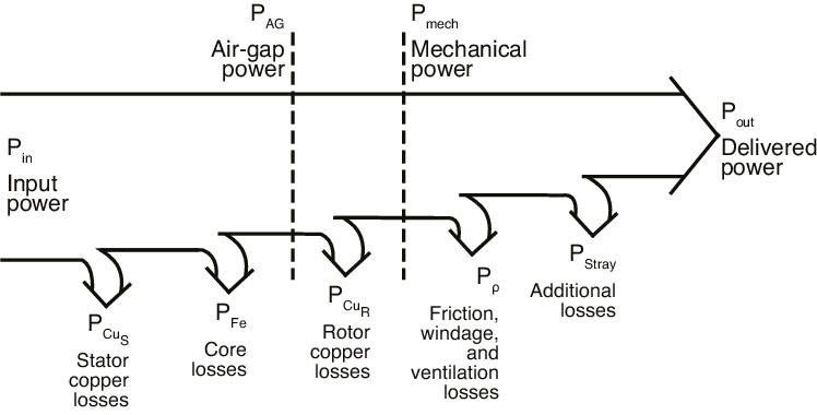
Motor Losses
For a DC Motor, if there are no mechanical losses which is induced by a counter-torque.
For a separately excited DC Motor:
and our power losses are given by:
Ignoring losses
Usually in a question, if you need to ignore losses the question will ask you to ““ignore mechanical losses” or “assume no armature reaction at which point “
Efficiency
Where is just the sum of all the losses.
Some side notes about power
- Forced air cooling and liquid cooling is used to cool machines
- Sparking can wear down brushes and commuter segments where the power loss from the voltage drop associated with brushes in the prescence of armature currents is given by
Rotation Direction
To reverse the direction of rotation, you need to reverse the direction of developed torque by:
- Changing the direction of the armature current flow by changing the polarity of the armature voltage
- Changing the direction of the magnetic field You can have multiple combinations of and in terms of which is positive and negative to turn your machine into a generator or motor with different directions of rotation, the same thing applies with speed and developed torque
Magnetization Curve
so is proportional to where where recall here is resistivity.
on our curve…
Where where
Terminal Characterization
For the following motor…
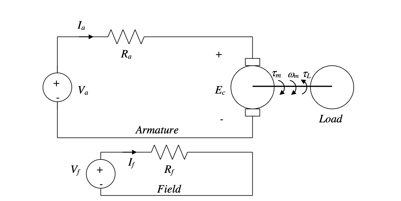
The main relationships are…
This ones pretty important
Where and just represents developed torque.
The terminal characteristic that relates n to is…
Speed regulation is given by…
This is typically 2-3% for separately excited and shunt DC machines
Equation of Motion
The equation of motion of a rotating object (in this case our rotor) is…
Therefore, to increase speed increase w.r.t
Starting Currents
Since is typically small, can be large. This causes high loss, damage, and eventually a short circuit.
This can be avoided using a low or inserting a series resistance with the armature. Note that high starting current means high starting torque.
Notes From Examples
Changing starting current to rated current ratio
Basically, there are two methods here:
- We can change the terminal voltage by solving for where we know and and the ratio
- We can also keep and solve for using Where is some adjustable resistance