Using Block Diagrams, you can describe a dynamic system and derive systems of equations
Controls
- A control system always consists of multiple subsystems
- We can model the big picture of a control system using only a few graphical symbols
Zero State Response
Symbols:
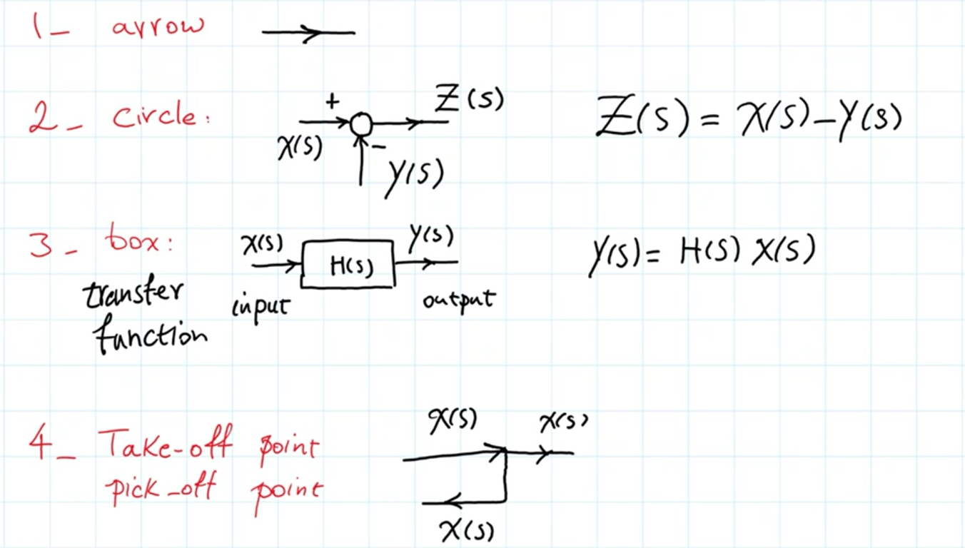
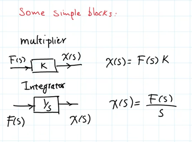
Simple Blocks:
Basically given a transfer function or an equation of motion, we want to draw the flow from the input to the output using these blocks and symbols.
Some weird behaviour to note, is that the input of a block does not necessarily have to agree with the output in terms of what exactly is being passed into the block and what is produced. Only the operation the block performs from the input to the output must agree.
For example, each output line will be X(s) where a series of integrators feeds into that (1/s)→(1/s) where you can get x(t)’ and x(t)” from the outcome of these blocks if you need then, and then use integrators or multipliers to add on constants and such.
Integrators
When creating block diagrams, separate out the integrators from regular division constants in separate blocks.
A couple other useful operations…
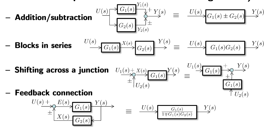
Simplifying Block Diagrams
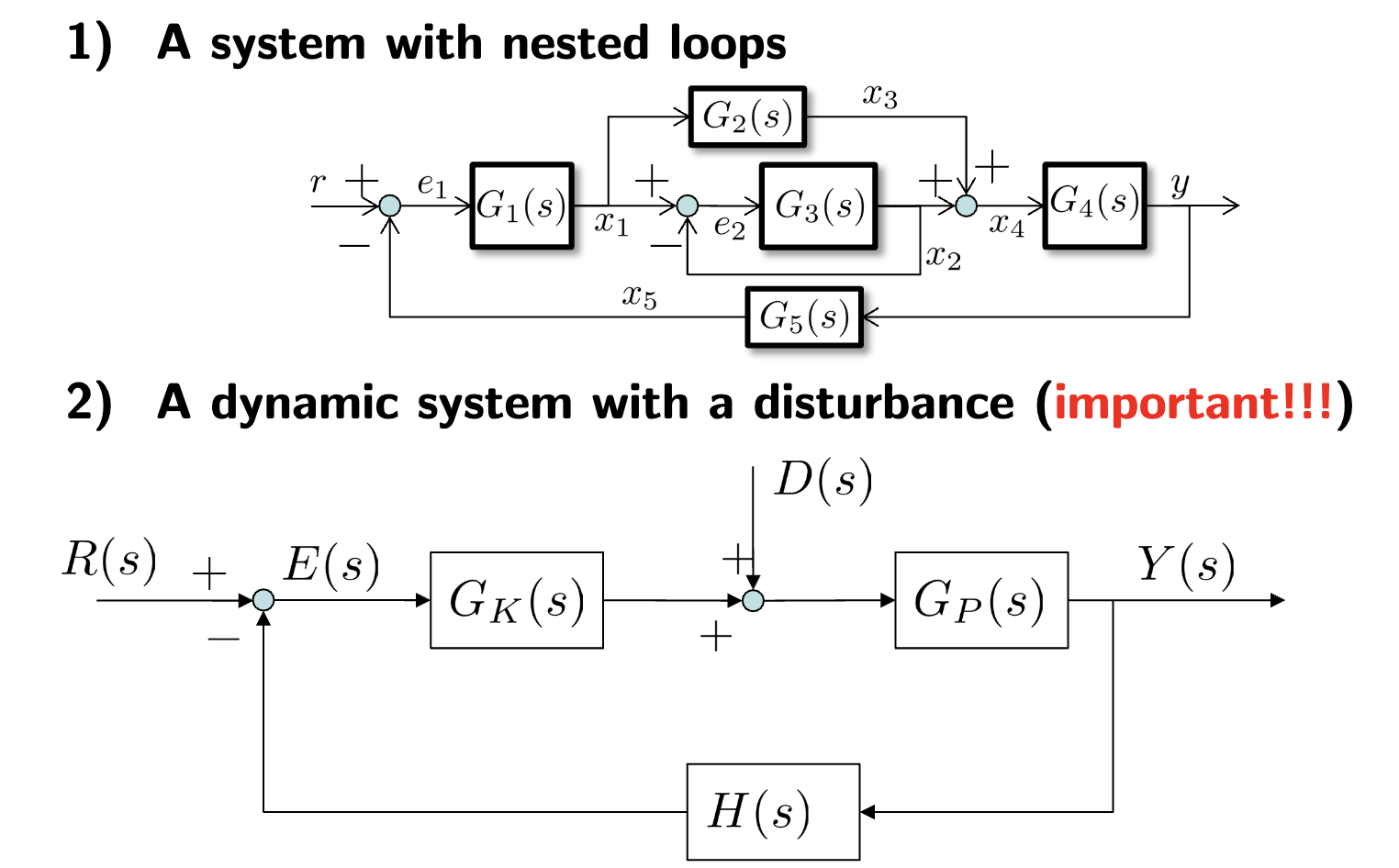
- Simplifying a system with a disturbance and simplifying block diagrams in general are important in this course
- is the gain at the plant (HW)
- is the gain at the controller (software)
- D(s) is our disturbance (things like friction)
Essentially, the strategy here is to Group parallel branches together and abstract away relationships into blocks. We can define the nodes at different junction as variables and use basically KCL at a junction to derive relationships for these variables. Then using these variables which are abstracted relationships, we can get our final relationship.
Obtaining Time Responses from Transfer Functions
- Get TF of a system
- Multiply Laplace transform of the input by TF to get Y(s)
- Obtain fractional decomposition of Y(s)
- Obtain y(t) by inverse Laplace transform