Frequency
In systems, this is a man made concept whereas the time domain is a physical concept.
The output of a linear Dynamic Systems is the transient response + the steady state response
We can represent a time signal as a sum of sinusoids and for any single sinusoid, we can represent that as a combination of sinusoids
If (on the imaginary axis), then is the system’s frequency response.
Where can be represented using Euler’s Identity
Frequency response is the steady-state response to a sinusoid (after the transient response disappears)
Where the first term is the amplification by the system and the second term is the phase shift by the system.
If we say that then the output where
Applications to 1st Order Systems
Transforming to the frequency domain…
so
If we say that then
Where the angle
Examining this at steady state…
Applications to Second Order Systems
Of this form…
Taking to the LaPlace domain…
The over-damped case
Two real poles of and
Once again subbing in
The underdamped case
Resulting in where…
Dividing by you send up with the frequency ratio as a term in the denominator
Simplifying, we end up with…
Summary Table
| |H| | <H | |
|---|---|---|
| and | 0 | |
| and | ||
| r→ | 0 |
Notes from solving
To solve the steady-state response of a function, you need to:
- Find a 1st order ODE
- Do the LaPlace transform
- Find the transfer function
- Find the magnitude of the transfer function
- Find the phase angle of the transfer function
- Assemble the steady-state response function in the following form
For a second order system
Expand to the form and convert to which yields which are your real and imaginary parts, then its just like normal.If your system has multiple parts like then solve with the s from each section (in this case its and ) and then follow the steady-state response function form to piece it all back together (there will be three terms where the all real term is something like )
Frequency Domain Specifications
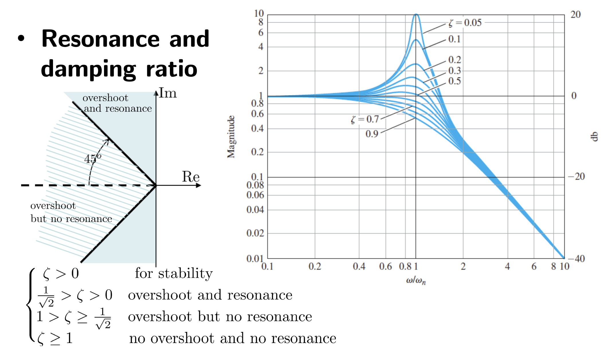
- Resonance peak : maximum value of this is not desirable and we should suppress this.
- Resonance frequency which is the frequency required to achieve 1.
- Bandwidth, : range of frequency that a system can normally operate, this is where the drops to of the DC gain
- Cutoff rate: the rate at which the high frequency signals are attenuated and is the slope of (in dB) at high frequencies which depend on relative the relative degree of the system (n - m (denominator degree - numerator degree))
For 1st order systems
For a standard form of
- Resonance Peak
- For a first order system:
- Where is a decreasing function of , thus there is n peak or resonance
- Resonance Frequency
- No resonance for a 1st order system
- Bandwidth
- For a first order system
- Cutoff Rate
- -20 dB/decade
For 2nd order systems
For a standard form of which can be represented as…
where
- Resonant Peak and Resonance Frequency
- Where
- Completing the square… this is the same as ¯
- If has a minimum at
- If Where is a maximum here
- The corresponding resonance peak is where K is your open loop gain, this becomes for the closed loop unity gain of 1
- If then is a minimum at and
- No resonance if
- We want this to be small
- Bandwidth
- gives the maximum bandwidth without resonance
- We want this to be large
- Cutoff Rate
- 40 dB/decade
