All of these concepts are heavily dependant on Bernoulli’s Principle
Pressure drop
Note that pressure drop is given by…
As in the case with many flows, characteristics differ based on the Reynolds number…
In general…
- = Laminar
- = Transitional
- = Turbulent
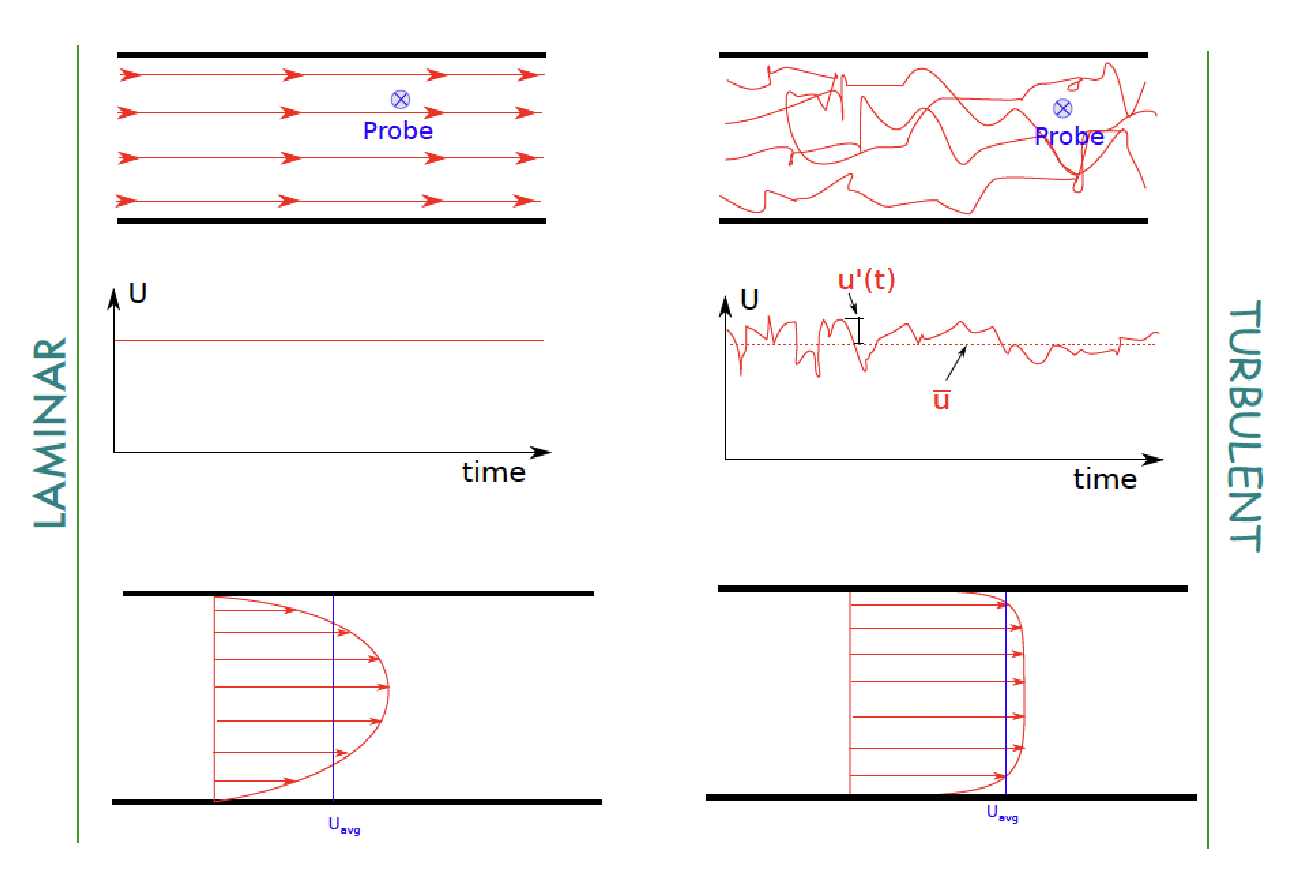
v is the measurement at the probe…
Laminar vs Turbulent Flow
The velocity profiles differ based on the type of flow being introduced…

Assumptions
For turbulent flow, the 1D assumption for the velocity profile is better than for laminar flow
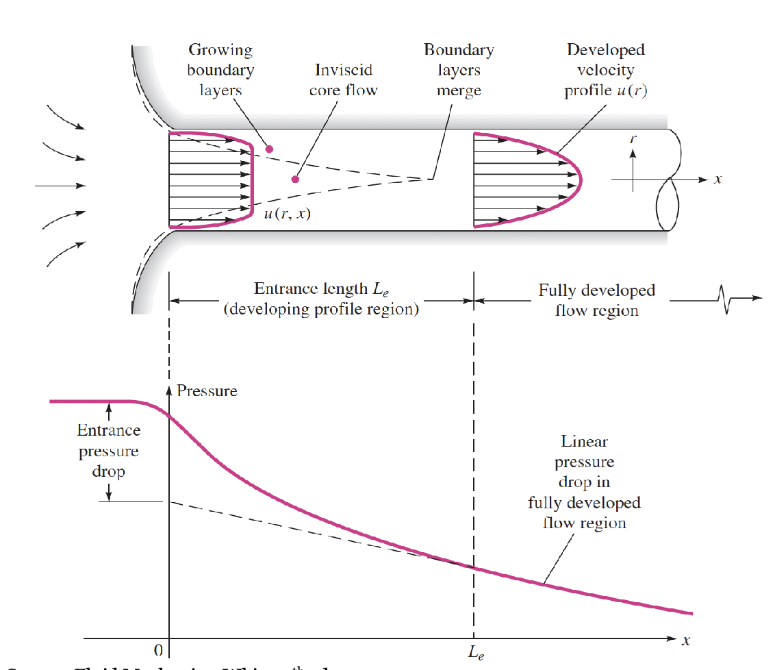
Initial Development of Pipe Flow
- Growth of viscous boundary layers means core flow needs to accelerate to satisfy continuity
- Entrance length can be long depending on the Reynolds number
- Here, the length is the length for flow to be fully developed

Losses
Note that losses are referred to here as “head losses”
Entrance Length and Losses
- Depends on the Reynolds number of the fluid
- If the pipe length / Diameter is small , we neglect entrance losses
- For a short pipe, entrance losses can be significant
Frictional Losses in Fully Developed Flow
Here, we have capped velocity profiles that look like the pipe flow above, with (wall shear stress (technically ) but I write it how I write it leave me alone) moving to the left. Here, there is no assumption about laminar or turbulent flow…
Here…
where Conservation of Momentum is used to get the frictional loss…
- Where you end up with
Friction Factor
General Model for Losses
- Minor losses:
- When there are additional components in the piping system – bends, expansion, contractions, valves etc. there are additional pressure losses (more mixing)
- These losses are called ‘minor’ loss, though they can be significant
- Friction losses:
- Use this if the question says the pressure drop is the same!!!
Laminar Flow
- is given as equation 1…
- For Laminar flow:
- To get we use @ r=R and sub into equation 1
- This yields…
Turbulent Flow
- Roughness is important
- Continuous range of scales
Comments
- As Re increases, the flow has more inertia relative to viscosity
- Empirically, as f decreases, Re increases
- The friction factor can also be a function of pipe roughness
- For laminar flow, f is not impacted by roughness
- For turbulent flow, f is impacted by roughness
- We can see friction factor relationships from a Moody Diagram
Comments on Roughness
- Roughness is quantified in a relative sense
- Roughness depends on pipe diameter
Types of problems
- Find the driving pressure (or head losses)
- Given the piping system (length, diameters, materials, Q)
- Find suitable pump or pressure drop in system
- The solution include finding average velocities, the friction and minor losses, and using Bernoulli to find pressure drop
- Find the flow rate given the system characteristics
- Express and as a function of Q
- Assume turbulent for laminar
- Guess
- Solve Bernoulli for
- Compute new
- Compute new
- Check if region on moody diagram matches assumption based on how close the new is from the old one, if its pretty close we have reached a solution, if its far off, we guess a new f to try to get the Reynolds number that we want
- Select a pipe (length, diameter)
- Given a flow rate, losses, fluid properties, pipe length
- Find the diameter needed for the pipe based on , as a function of
- Assume laminar or turbulent flow
- Solve for
- You may need to use symbolab, Matlab, or wolfram alpha for this since the eqution could be non-linear
- Check
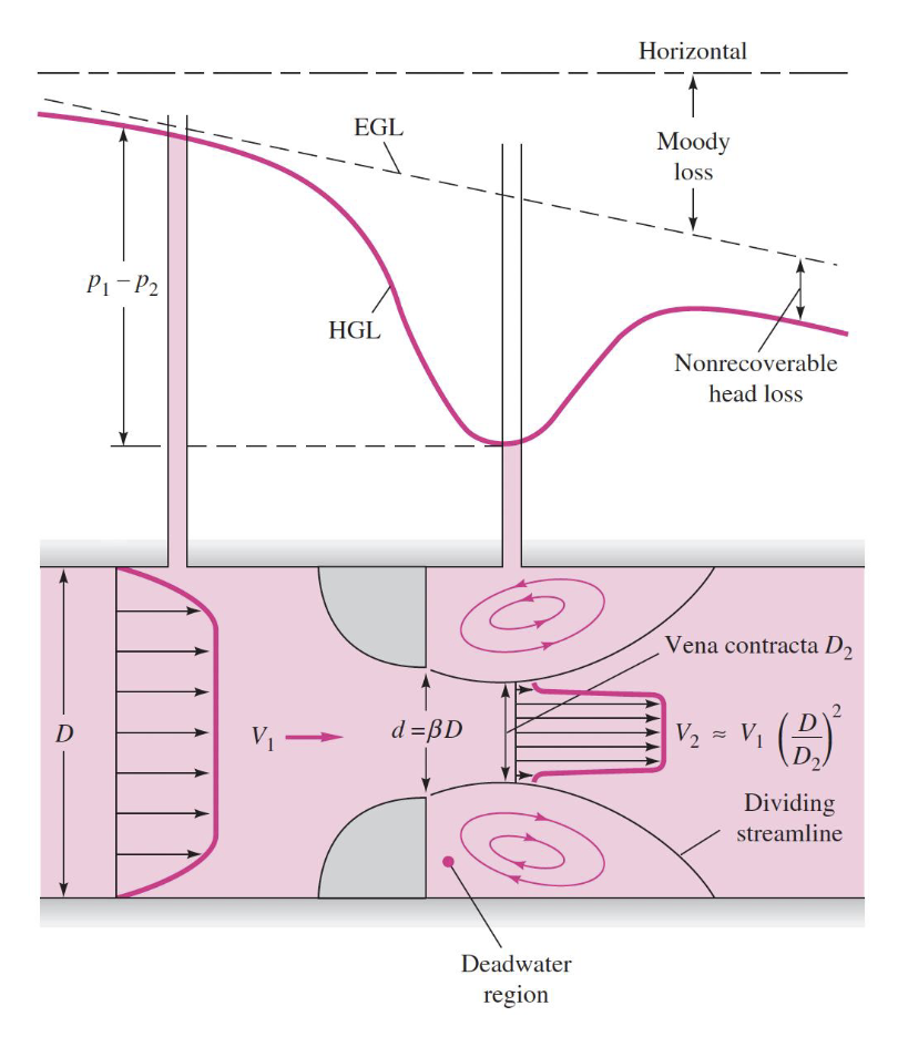
Orifice Plate

- One way to measure a flow rate is to put an obstruction in the flow and measure the pressure drop
- An orifice plate has some advantages in comparison to some devices
- : Pipe diameter
- : Opening diameter
- : Vena contracta diameter
-
- Where
- here is a loss coefficient
Hydraulic Diameter
Pressure loss due to friction for pipe flow
- which is laminar or turbulent and here is for perimeter For a pipe or duct with a different shape…
- where the bar indicates the “average” shear stress The definition of hydraulic diameter
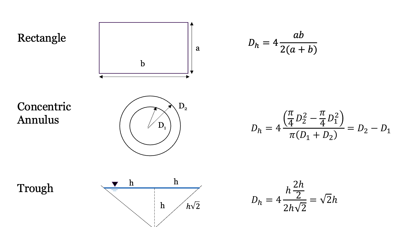
- This is the equivalent diameter for different pipe shapes and stuff
- In general this is
- Using our previous definition of and leads to where that last term is which is the hydraulic diameter
- Where we have different hydraulic diameter shapes…

Flow rate through a set of channels (screens, straws, etc)
- and
- Where
- and is the same for each channel!!!