How it works?
The magnet and coil rotate in the same direction but the magnet moves a little faster than the coil so the coil feels like its moving in the opposite direction which induces a current in the coil which creates a force to keep the motor rotating in one direction…
We can create the same effect by sending a sinusoidal to the fixed stator coil.
Single Phase
- Rotating field with a single phase to create a phase shift
- 2, 4, 6 pole configurations are common
- Poles are connected to the same power source and see the same sinusoidal cycle Many of these are implemented with Three Phase Circuits where the field pole windings are physically located at a 60 degree offset and each phase behaves as a single-phase 2-pole motor creating a magnetic field.
Rotating Field (Single Phase)
- You use an auxiliary coil with a phase lag (capacitor)
- This is a capacitor start induction motor where a single phase is split into two which acts roughly like a 2 phase motor but only uses one phase
- There is also the shaded pole method where you use a small copper ring as a secondary coil (2 poles here)
Synchronous Speed
This is the theoretical speed that the rotor should rotate at, if it could perfectly follow the magnetic field rotation based on sinusoidal frequency. The frequency of the motor is the same as the frequency of the input phase.
- The magnetic field at 0° corresponds Notes
- Single phase
- 2-pole: 1 rotation for 1 AC cycle (2 pole shoes)
- 4-pole: 1/2 rotation for 1 AC cycle (4 pole shoes)
- Two phase
- 2-pole: 1 rotation for 1 AC cycle (4 pole shoes)
- 4-pole: 1/2 rotation for 1 AC cycle (8 pole shoes)
- Three phase
- 2-pole: 1 rotation for 1 AC cycle (6 pole shoes)
- 4-pole: 1/2 rotation for 1 AC cycle (12 pole shoes) Ideally, synchronous speed is then
- where f is the AC power frequency in Hz and P is the pole number.
- You can also use angular frequency is you convert it Note that the synchronous speed is always a little slower than the angular velocity of the rotor (motor)
- Since , we can define slip as…
Torque Speed Characteristics
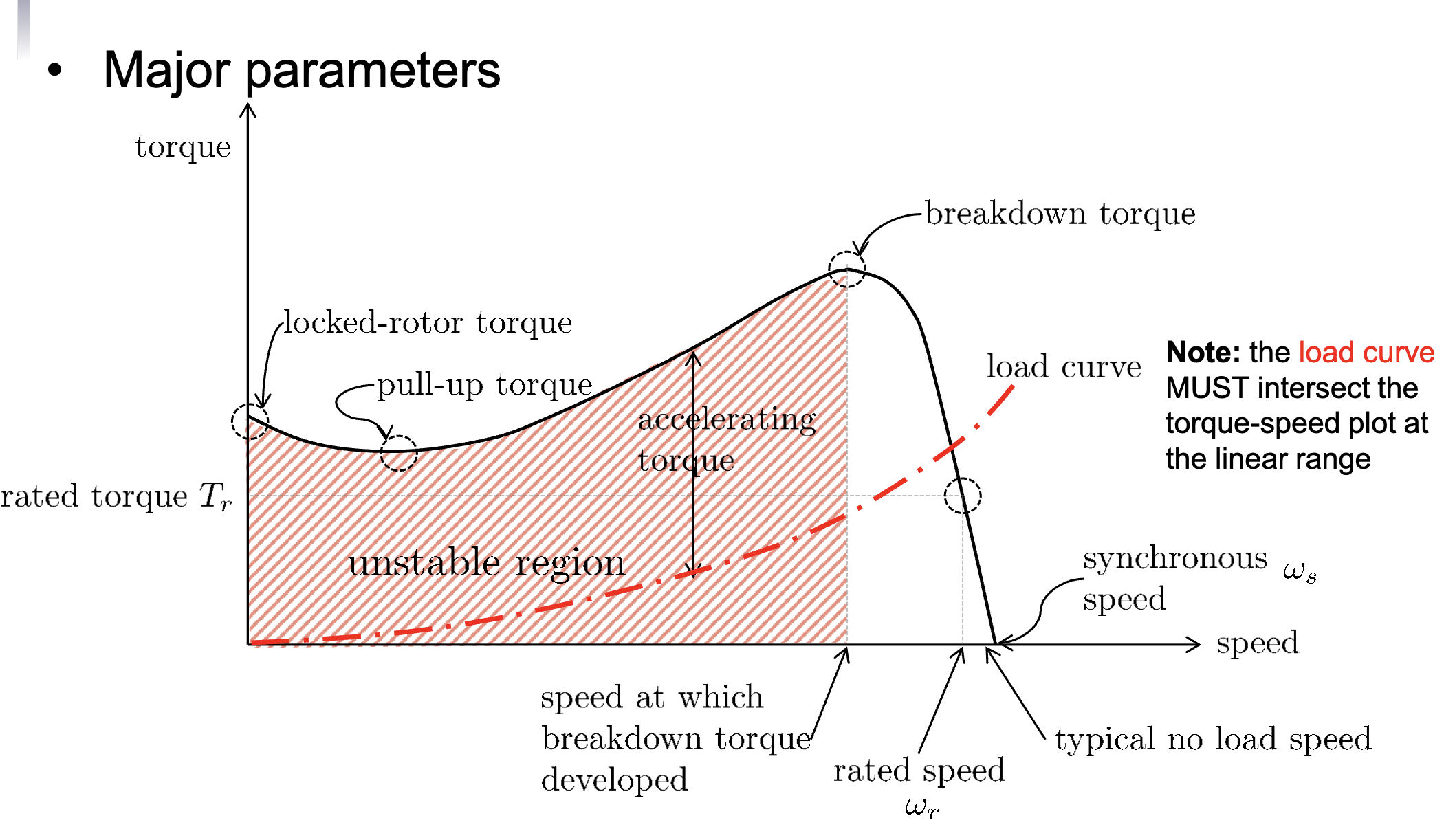
- The load curve must intersect the torque-speed plot at the linear range…
- You can solve these questions with a similar triangles approach

The Major Parameters Here Are
- Locked-rotor torque (starting torque): The torque at zero-speed
- Large load machines need a high starting torque
- Pull-up torque: The minimum torque during the transient period
- Break-down torque: The maximum torque available during the acceleration period before the motor reaches its full-load torque (nominal torque)
- Full-load torque (rated torque): the torque required to produce the rated power at full-load speed (rated speed)
- Service factor (S.F.): the percentage multiplier of rated power (or load) that the motor can operate for a short time without overheating
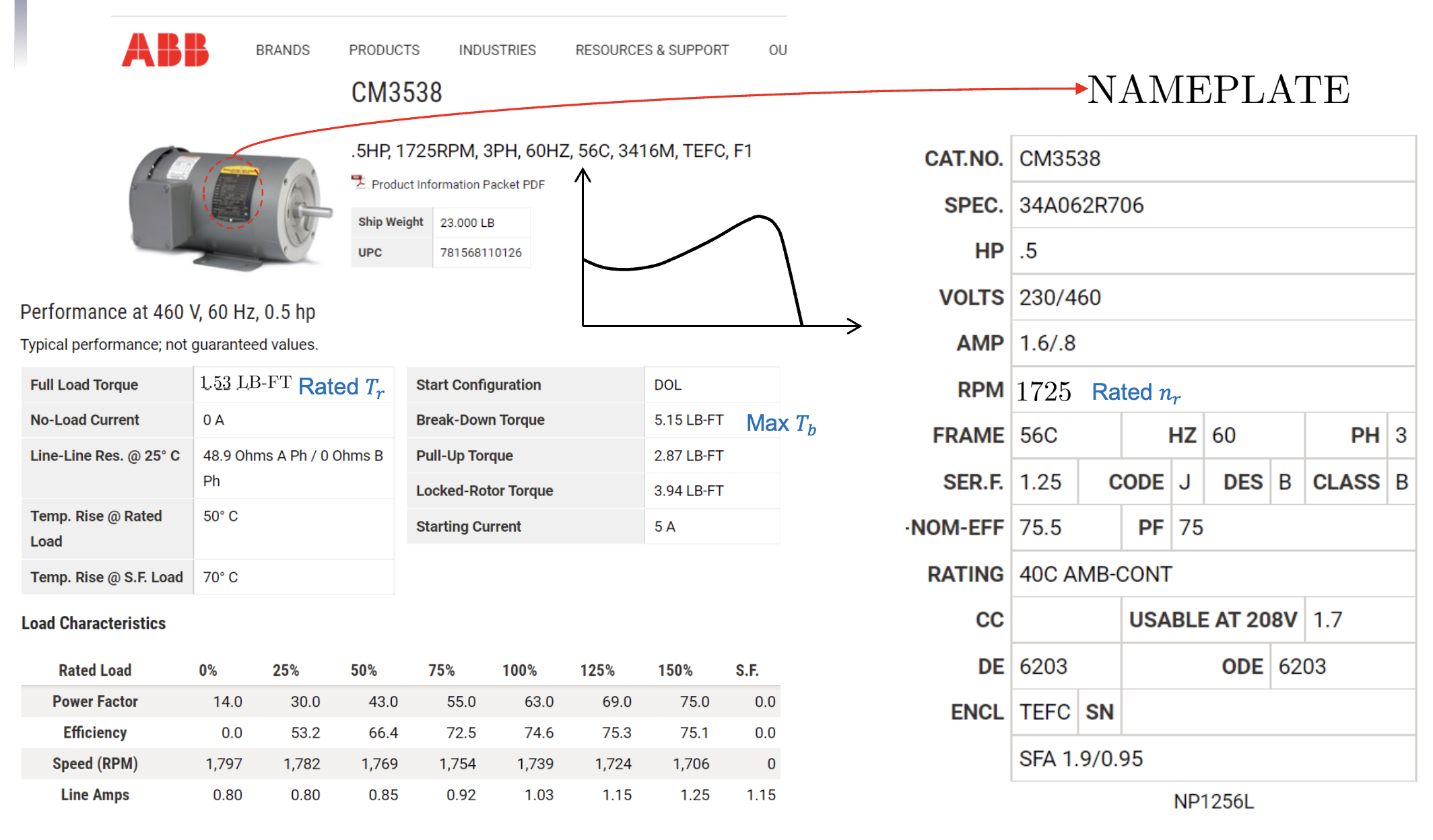
Given a nameplate, you can find these specifications through something like the following…

- Here you can find important things like…
- Rated torque
- Breakdown torque
- Pull up torque
- Lock torque
- Rated power
- Rated speed
- Service factor
- Phase and frequency
- Starting current
PWM for Inverter
- 3 phase inverters and variable frequency drive using transistors and PWM can control the amplitude and frequency of your motor but AC motors are not generally used for speed control